Eta-2 Interceptor — 3D modelling
A SolidWorks modelling study, from visual references and proportion studies to a detailed 3D model and rendered views.
Project
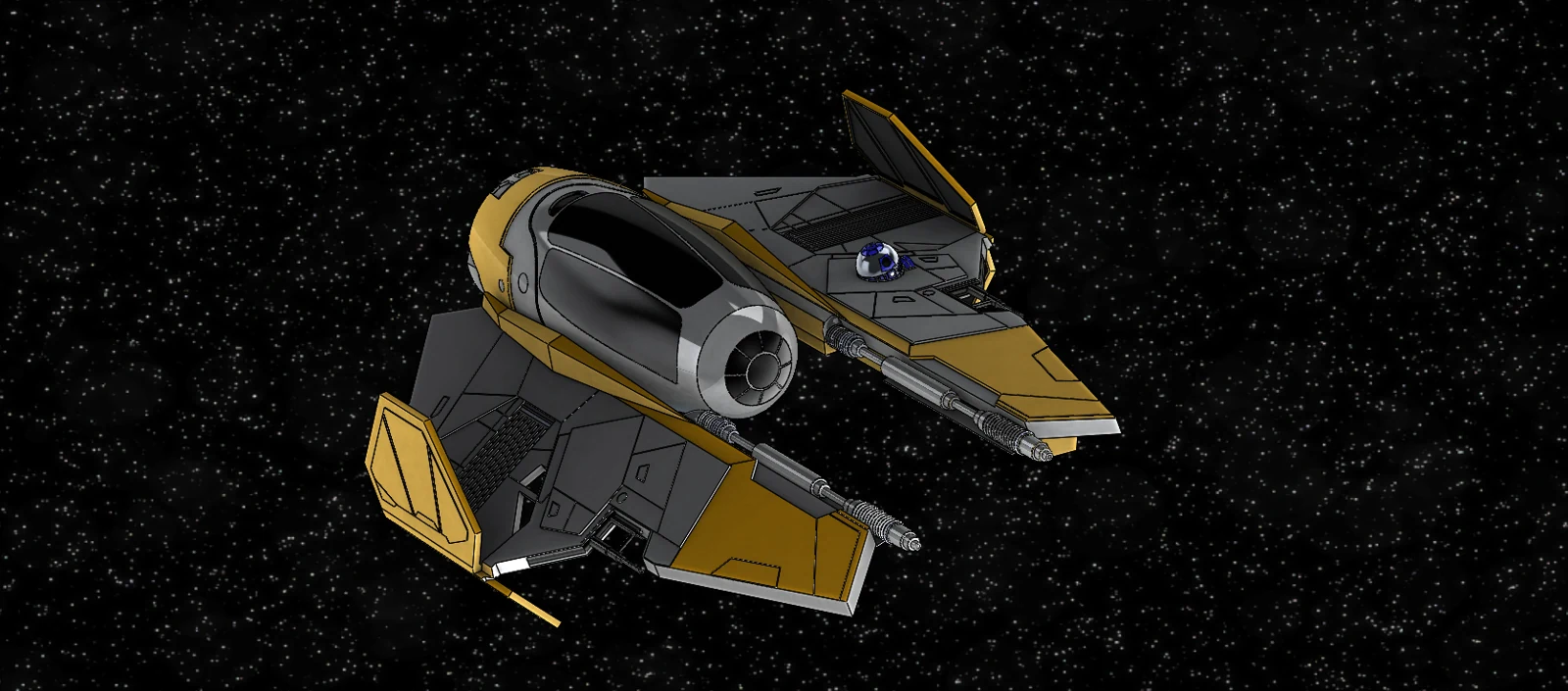
A four-month Machine Design project at ESILV, developed with Hugo Bessis. We reconstructed the Eta-2 Jedi Interceptor from Star Wars in SolidWorks, using its complex geometry to practise solid and surface modelling, feature construction and visual presentation.
Reconstructing proportions
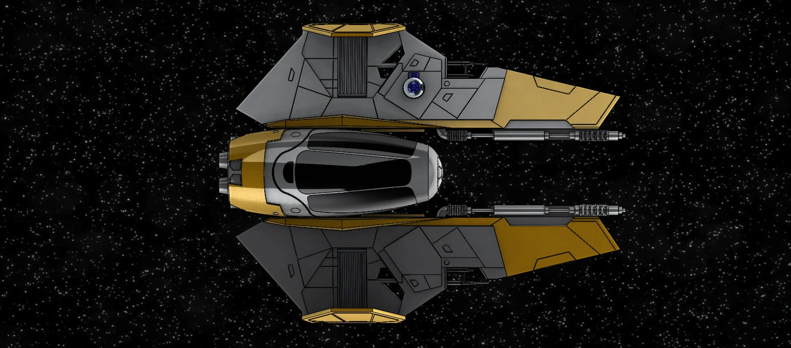
The project began with a collection of reference images, published dimensions and an existing 3D reference model. We measured proportions in the images and converted pixel measurements into dimensions to guide the SolidWorks construction.
The work involved translating a visually complex object into sketches, features and bodies: the central cabin, wing geometry, rear propulsion units and smaller surface details. The reference material guided the shape; we built the CAD geometry for the course project.
Building the geometry
We used extrusions, cuts, fillets, mirrors and repeated features for the main forms and details. More complex areas required boundary features, sweeps, wrap features and additional reference planes. The cabin was a particular challenge because its surrounding geometry needed several construction approaches.
A change to the overall proportions midway through the project affected many dependent features. Reworking these dependencies became a practical lesson in how the feature tree influences later revisions. Another difficulty came from initially combining the wings and cabin in one body, which complicated mirroring and required changes to the body structure.
Collaboration and my contribution
Hugo Bessis and I worked on a shared SolidWorks document, taking turns and exchanging successive versions through a shared drive. The project went through more than twenty versions over the semester.
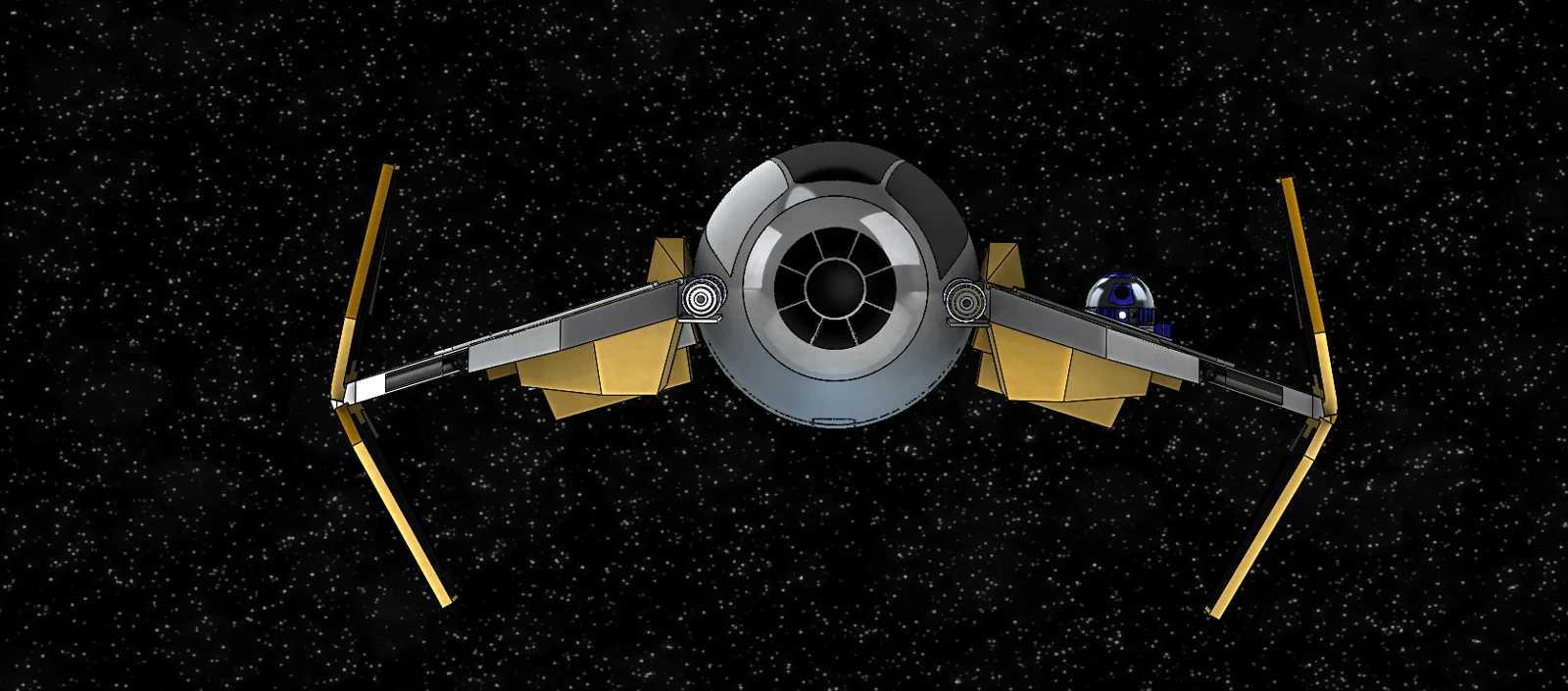
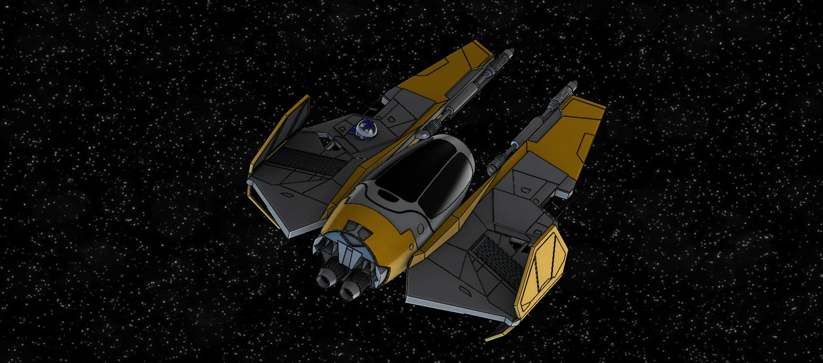
My main contributions were the overall vehicle form, cabin, wings and the small R2-D2 model. Hugo focused primarily on the central and lateral cannons, rear propulsion units, wing details and folding panels. Both of us also revised geometry created by the other, so the final model reflects a shared construction process.
Renders and lessons learned
The final model was presented through rendered views showing its overall proportions, front profile and rear geometry. The images on this page are selected from the project’s own render exports.
The project highlighted the importance of modelling structure: organising bodies, anticipating symmetry and managing dependencies between features. In our review, we identified separate part files followed by assembly as a more suitable workflow for future collaborative projects. This would support parallel work and reduce the impact of local geometry changes.